EVBG STAFF July 20, 2023 EV Builders Guide
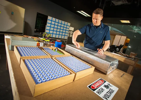
The blank canvas. One part opportunity, one part frustration. Be it a lump of clay or an empty engine bay, when the possibilities are endless, where do you start? For an EV builder, one of the biggest challenges is to decide where and how to place all those batteries needed to get their motor spinning in a way that is both safe in design and slick in appearance.
A great way to start painting a blank canvas is to give yourself constraints that guide your work. So before you start building your own EV battery pack, let’s familiarize ourselves with some examples of industry best practices to help you design a bespoke battery pack for your EV repower!
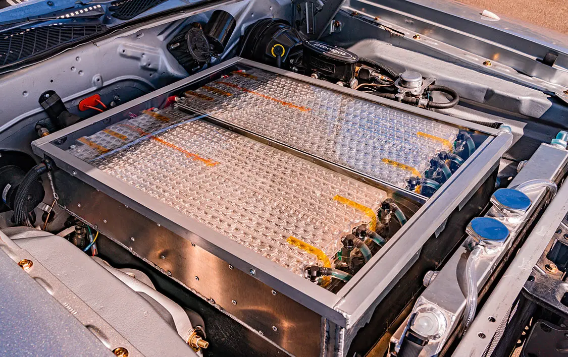
Full disclosure: Battery pack construction is often considered to be the Wild West of the EV industry. There is a lot of opportunity but a significantly larger amount of danger. The notes below are a thought exercise for what to consider before building your own pack. As the industry grows, more standards will develop, and pack development will become a safer and more standardized process.
However you decide to put together your battery pack, there are certain requirements that the finished pack should have to meet industry standards:
Ingress: Batteries need to be protected from exposure to substances that can affect their performance, such as moisture and dirt. Battery packs that are protected from water or dust ingress keep environmental solids, liquids, and gasses from entering the pack.
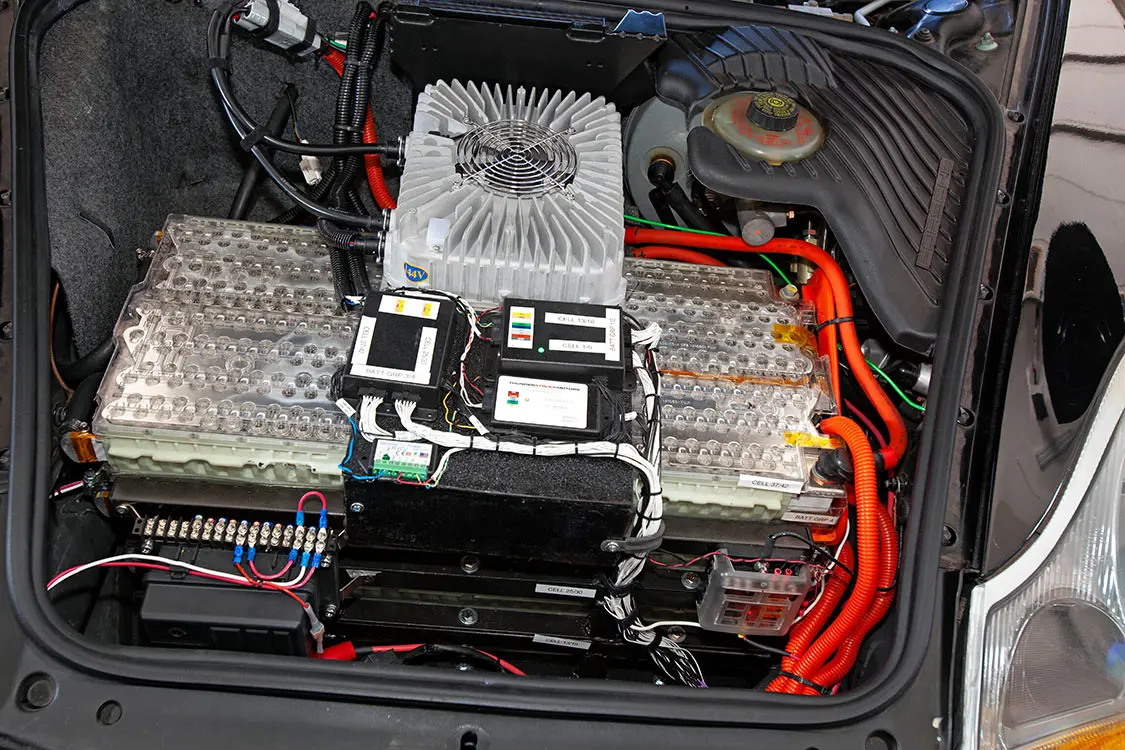
Vented: Battery packs can house thousands of individual cells, meaning there is a significant amount of air in the pack that can fluctuate in volume as the driver travels through different altitudes and temperatures. Furthermore, while lithium-ion battery systems do not release flammable or toxic gasses under normal operating conditions, they will release gasses under failing conditions, such as during thermal runaway. Most EV battery pack vents use dual-stage venting to make sure pressure remains equalized under normal operation, and that excess pressure can be vented quickly in the case of thermal runaway.
High Voltage Battery Disconnect (HVBD) and Manual Service Disconnect (MSD): When you need to service your vehicle, how can you be sure your high voltage circuit is de-energized? A HVBD and an MSD both separate the power circuit from the battery to ensure that anyone, be it you, a technician, or a first responder, can interact with your vehicle safely. In most OEM EVs, an MSD is used to isolate the battery pack from the rest of EV. The difference between an MSD is that the MSD is often fused and connected directly to the battery pack, while an HVBD is often more accessible and is simply a two-position switch. At a minimum a pack should contain an MSD as close to the pack as possible. An HVBD is great to include on the vehicle in a more accessible position in case of an event where a first responder needs to turn power off to the vehicle or if an owner wants greater ease of access to the high voltage turn-off (since the MSD is often difficult to reach being close to the battery pack).
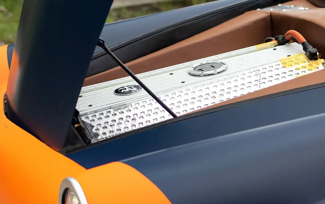
Insulation and Isolation: The last thing you want is 400 volts of electrical potential where it should not be. Plastic or rubber insulation should be used to prevent potential short circuits between metal-on-metal connections, like those made using busbars. Insulation creates the isolation of the high voltage that is necessary for a pack. A lack of insulation could create a loss of isolation and short to the chassis ground, meaning the high voltage would be present on the chassis of a vehicle, which presents a significant safety hazard.
Fusing: The closer the fusing is to the power source, the safer your design. Fusing at the power source ensures that all supply cables are protected. In most cases, the fuse is built into the MSD.
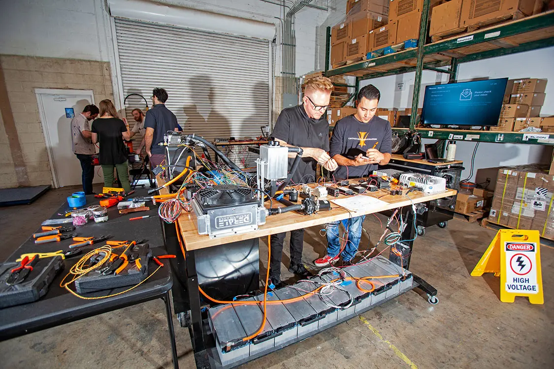
Thermal Management: Battery voltage, cycle life, charge, and discharge are all influenced by battery temperature, which the thermal management system works to keep in check. The chemistry of a battery, c-rate, its size and shape, and the load placed on the battery as well as the operational conditions will influence your thermal management approach. You can use passive thermal management, which uses natural conduction, convection, and radiation to cool the battery. This is the simplest option from a building perspective but could limit performance in extreme conditions, such as cold, heat, and high-power output applications. Alternatively, you can use active thermal management, most often in the form of liquid cooling and heating. This approach introduces significantly more complexity in a build but gives you great control over the temperature of your batteries.
You can build a pack from the cell, module, or pack level. Which option you pick will depend on a number of factors, including (but not limited to) your level of electrical knowledge, fabrication skills, appetite for troubleshooting, and the depth of your pocketbook.
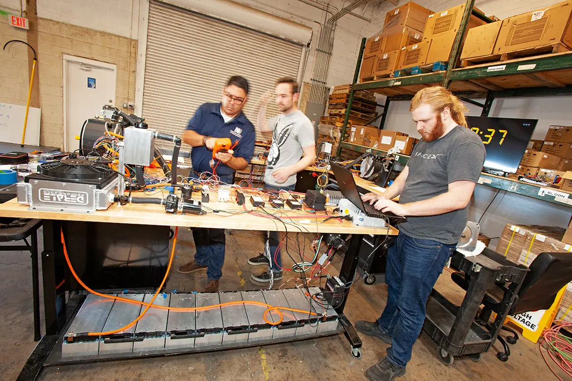
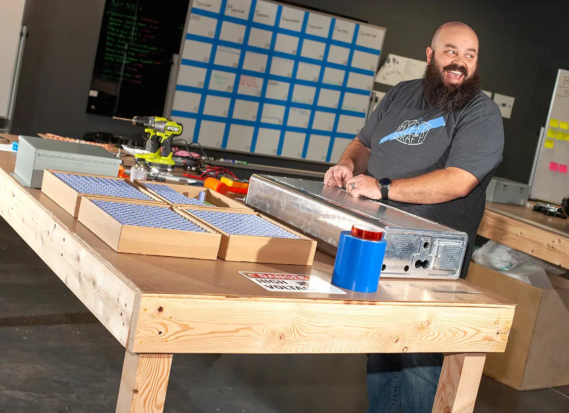
Cell Level—Your Blank Canvas Awaits: A cell-level pack build gives you the greatest degree of customization because you are arranging each and every cell, busbar, and BMS connection in your pack. You’re also going to build an impressive amount of muscle memory making the tedious connections between your cell groups and BMS, so bring a comfortable chair to your wiring room.
…battery pack construction is often considered to be the Wild West of the EV industry. There is a lot of opportunity but a significantly larger amount of danger.
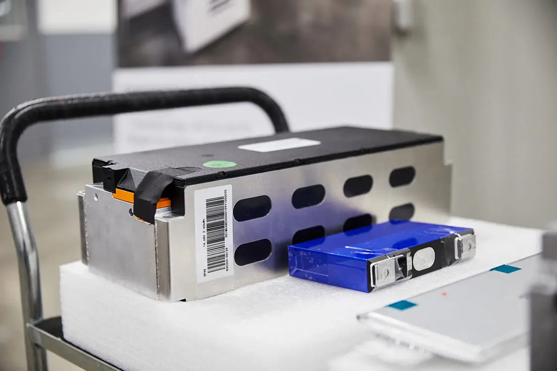
Module Level—Plug and Play, for a Price: If you would prefer to skip the step of harvesting a battery pack, you can purchase pre-harvested, refurbished modules from an OEM or purchase pre-made modules from a number of battery manufacturers. While this option can be more costly, you reap the benefits of a modular, scalable design that comes with cell taps installed at the cell level and pre-connected cells in a protective case. Not only that, but most modules are equipped with either cooling plates or internal coolant lines for active thermal management.
Pack Level—Some Disassembly Required: Nothing is stopping you from buying a salvaged EV, harvesting its battery pack, and reconfiguring its innards for your own project. This can be quite the affordable option, and you reap the benefits of pack-level fuses, connectors, and harnesses. However, you are left with the responsibility of safely disassembling the battery pack and verifying the functionality of its modules.
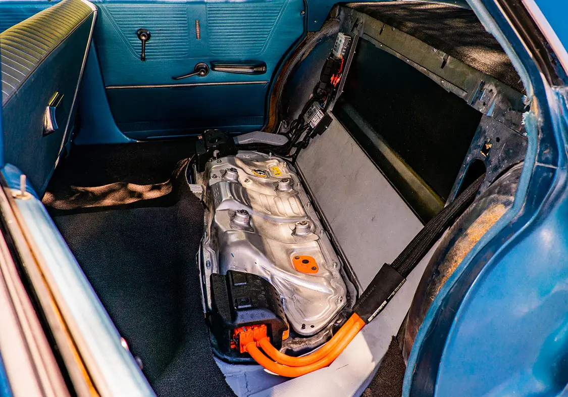
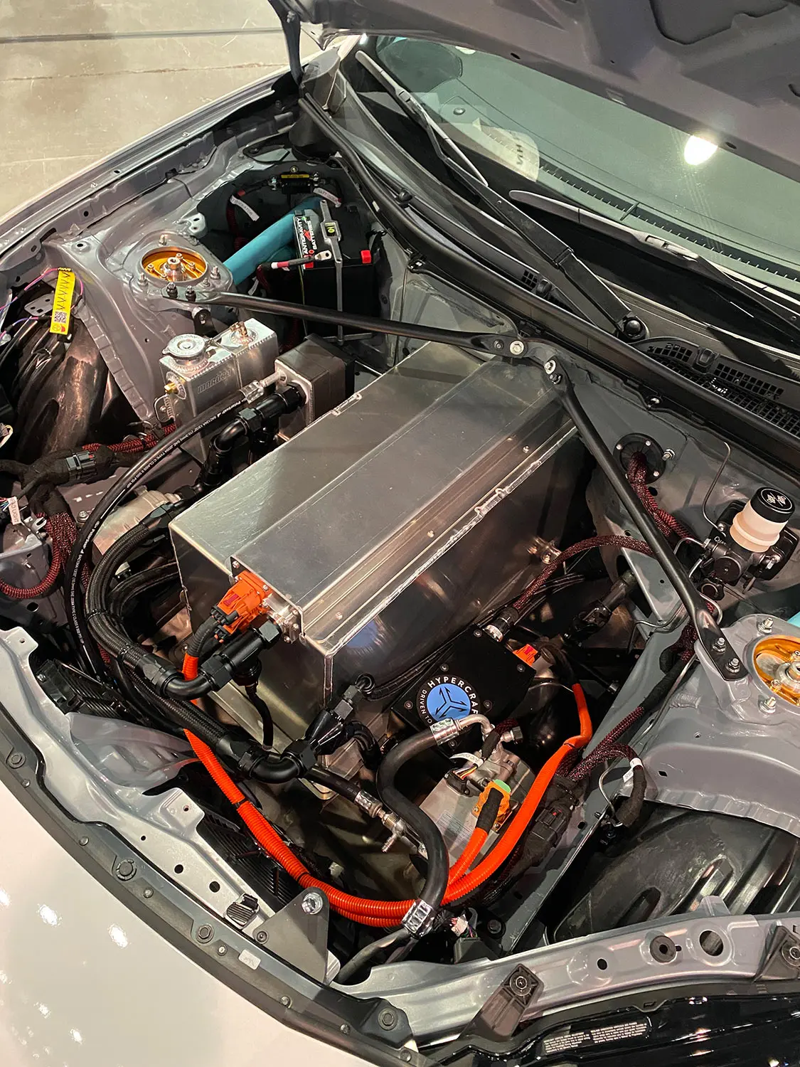
When it comes to the world of EV battery packs, we’re still in the Wild West. OEMs and DIYers alike are still experimenting with different chemistries, form factors, cell configurations, and thermal management systems. So while building a bespoke battery pack may feel like you’re staring at a blank canvas, know that there are options and strategies out there that can guide your process in designing a safe and sleek energy solution that will meet the unique needs of your build.
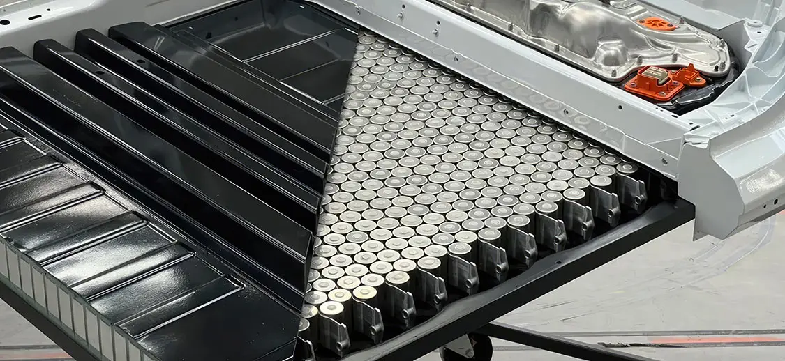
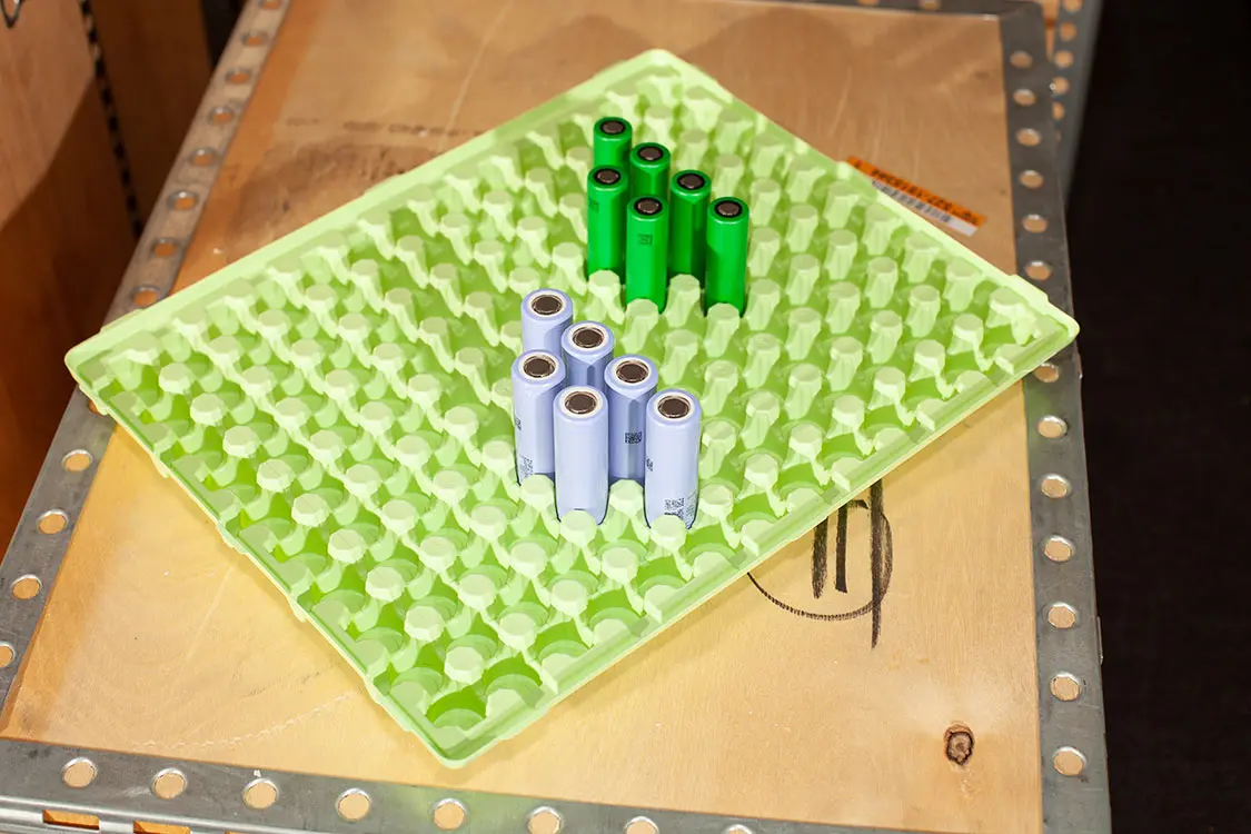
Size (and shape) matters when it comes to choosing cells to build your pack. Let’s explore the benefits and drawbacks of the three most common form factors of cell: cylindrical, pouch, and prismatic.
Benefits:
Drawbacks:
Benefits
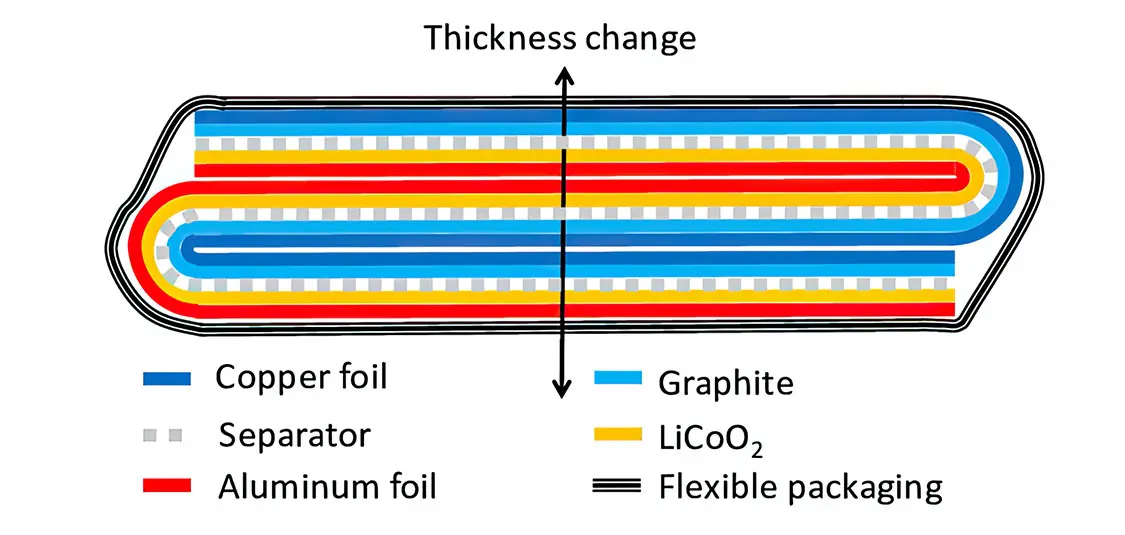
Drawbacks
Benefits
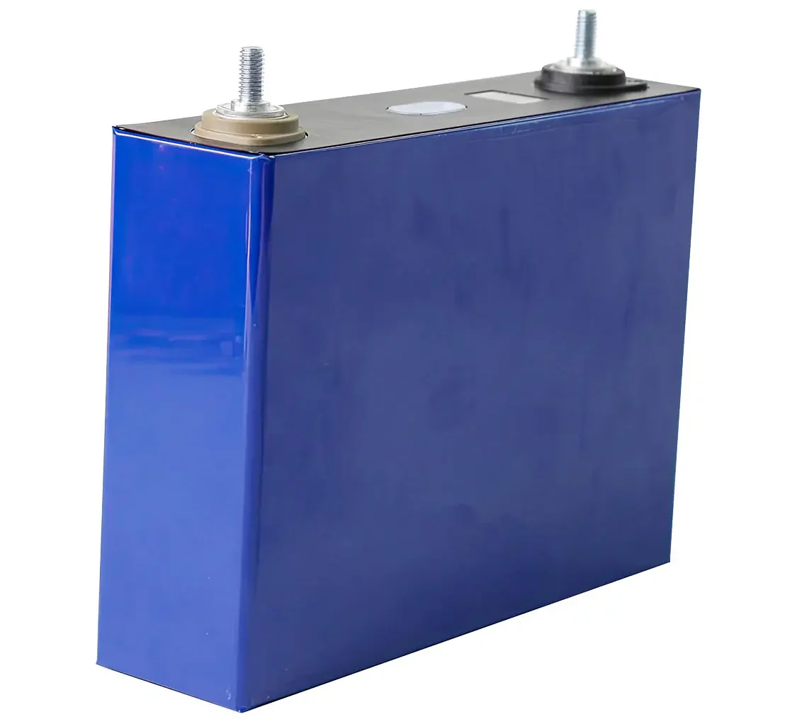
Drawbacks
There are growing module options for builders looking to create their battery pack from the module level.
VDA 355 Modules
Both Korepower and A123 manufacture VDA 355 modules. A VDA-sized module is set by the “Verband de Automobilindustrie” (German Association of the Automotive Industry). This group has proposed standards for the size of battery cell technology used in the automotive industry. A VDA 355 module specification of 355x151x108mm. This allows for consistency in size and power, while affording different voltage and capacity configurations to meet the needs of your build.
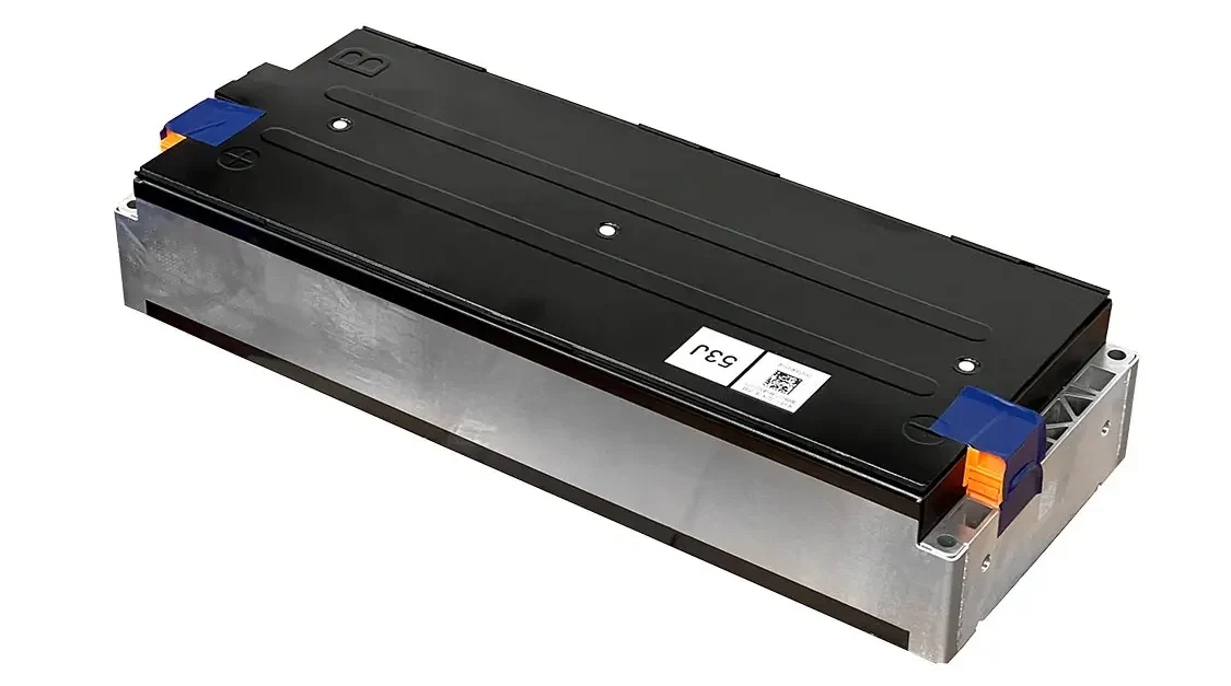
LG Chem Modules
Composed of seven pouch cells wired in series, the air-cooled JH3 64Ah battery module by LG provides a lightweight and high-performance solution for EV builders.
Tesla Modules
Tesla Model S modules come with 444 individually fused cylindrical cells in a 6S74P configuration. As part of the integrated cooling system, each row of cells is isolated from the next by a cooling pipe covered in thermally conductive and electrically insulated material running a mixture of water and glycol to keep the cells operating optimally.