Motortopia - EVERYTHING Automotive!
Exciting News! Motortopia App Now Available on Apple App Store!  
Close Ad

Upgrading a ’94 Silverado with New Vintage CFR Series Gauges: A Step-by-Step Guide

New Vintage USA June 28, 2023 Chevrolet

Follow Along as we Install CFR Series Gauges in a ’94 Silverado

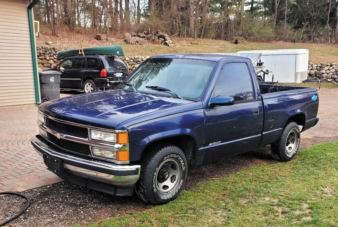
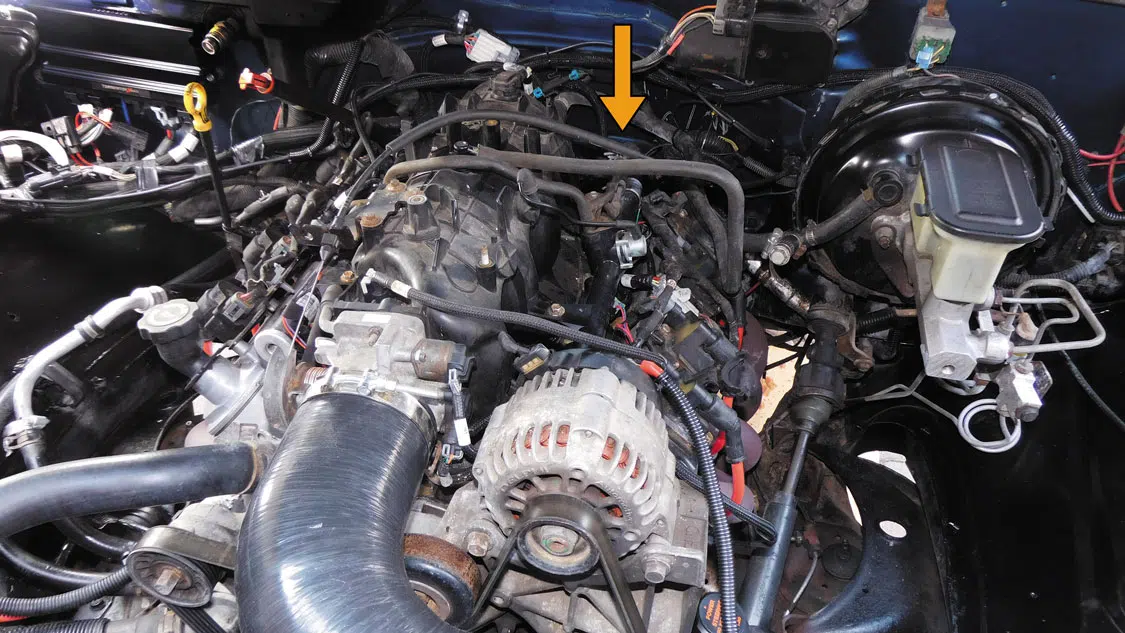
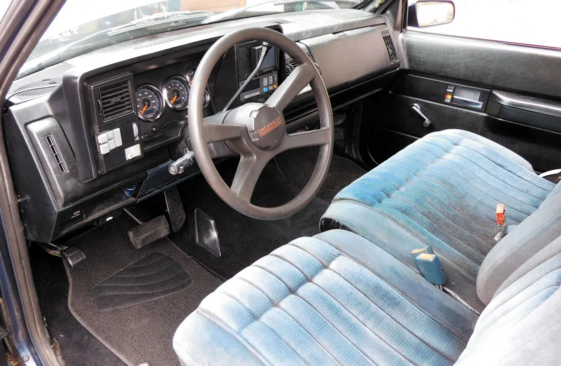
We began our search for a shop vehicle and happened to come across this blue ’94 Silverado with an LS swap that popped up on marketplace in Ohio. Because it was only about an hour and a half drive, we decided to make the trip. The truck was pretty solid, and the owner was a rac-ing enthusiast who had taken good care of this OBS. After a quick tune-up and some extra cleaning, the truck was ready to become our new shop truck.

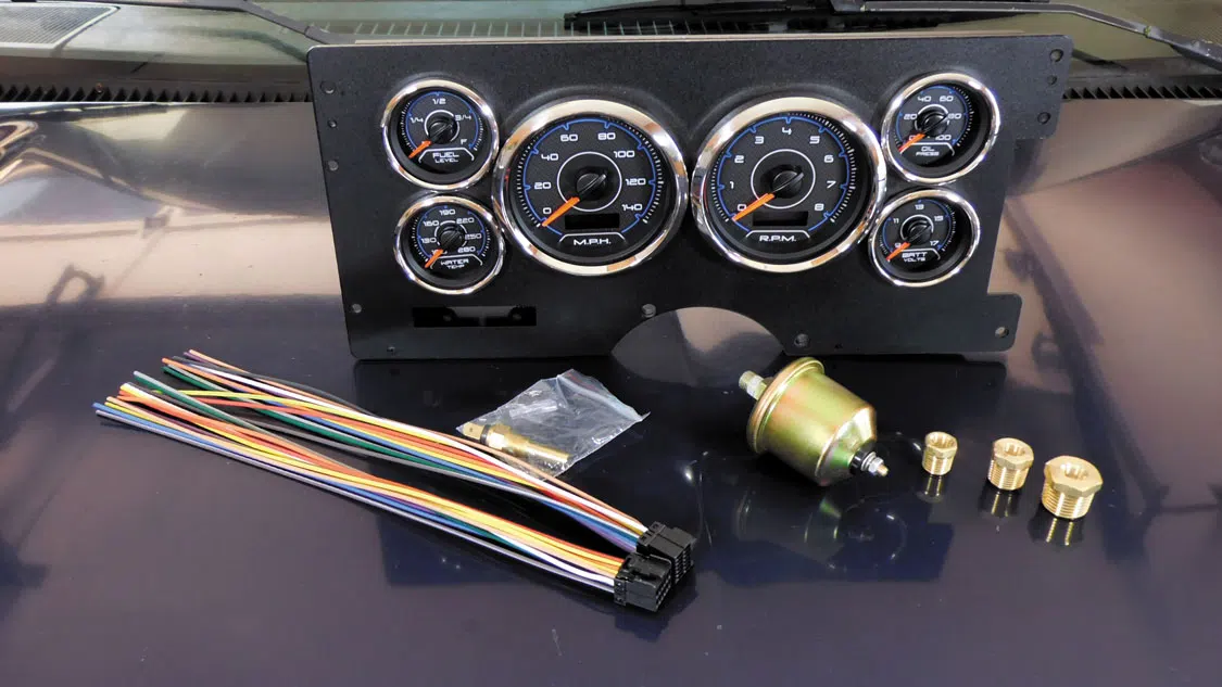
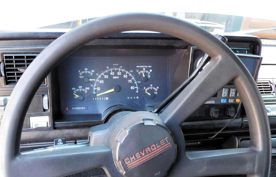
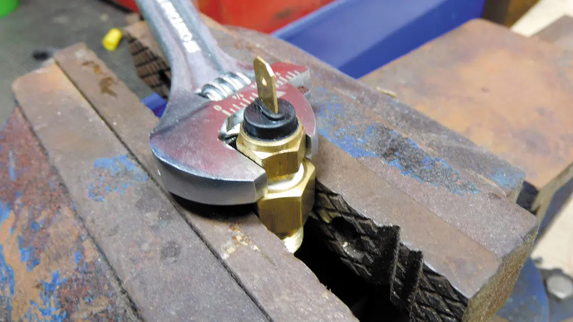
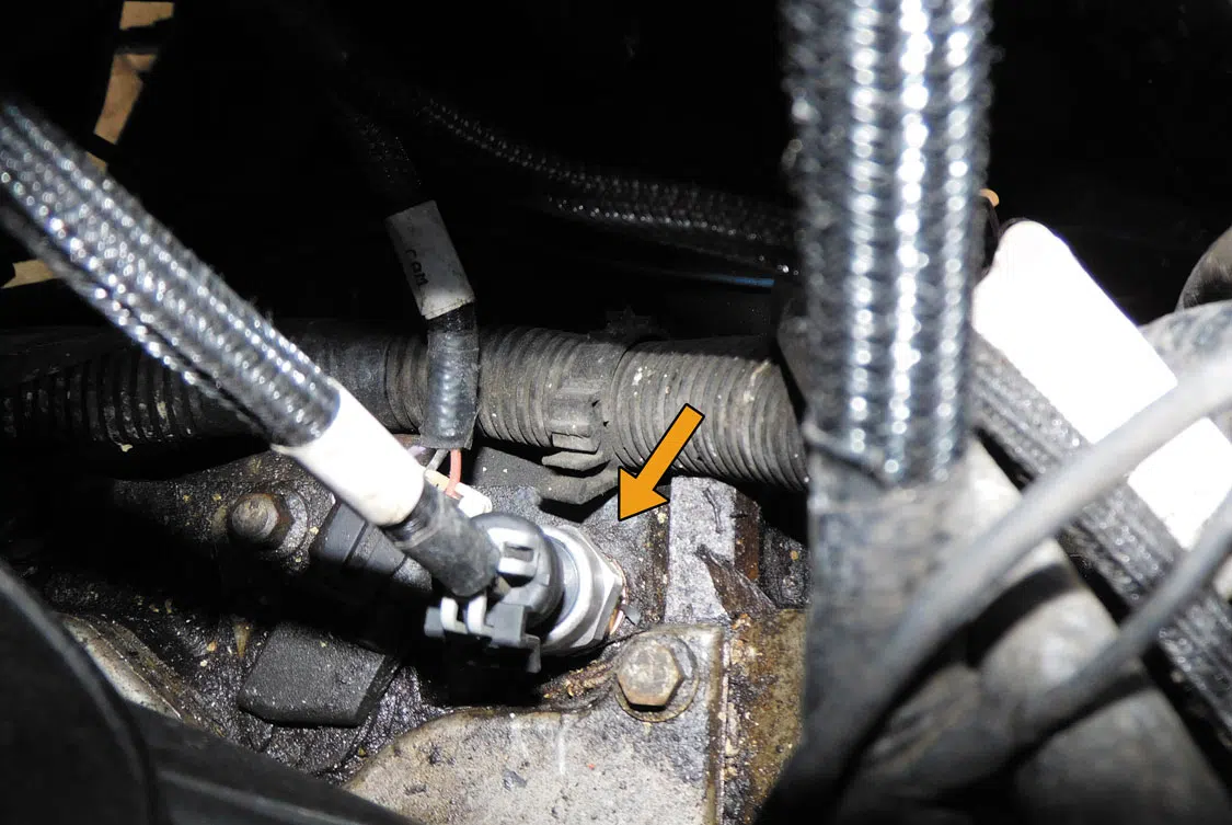
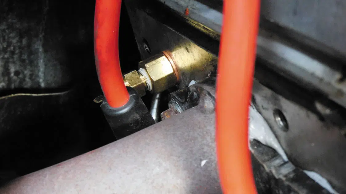
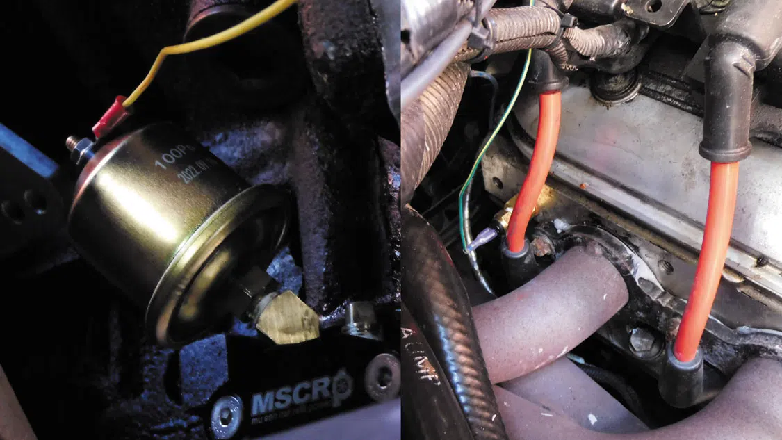
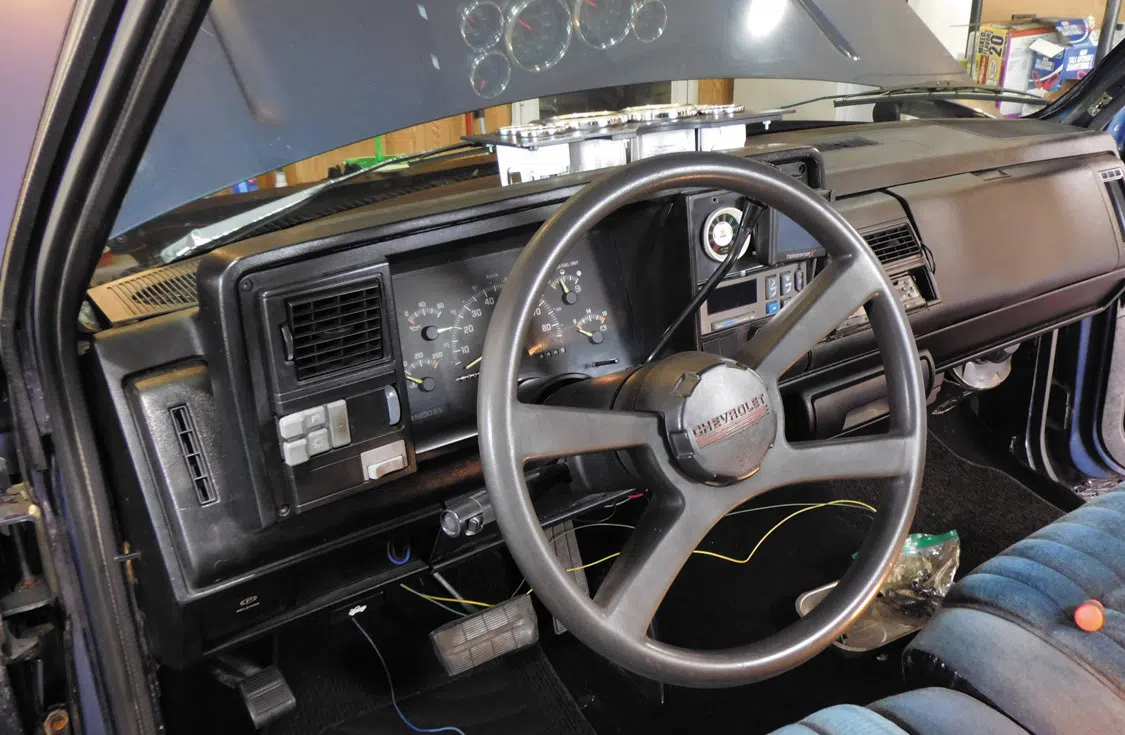
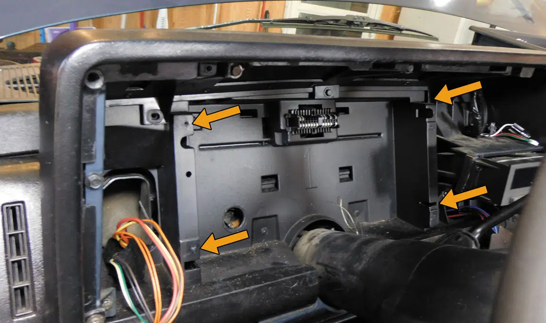
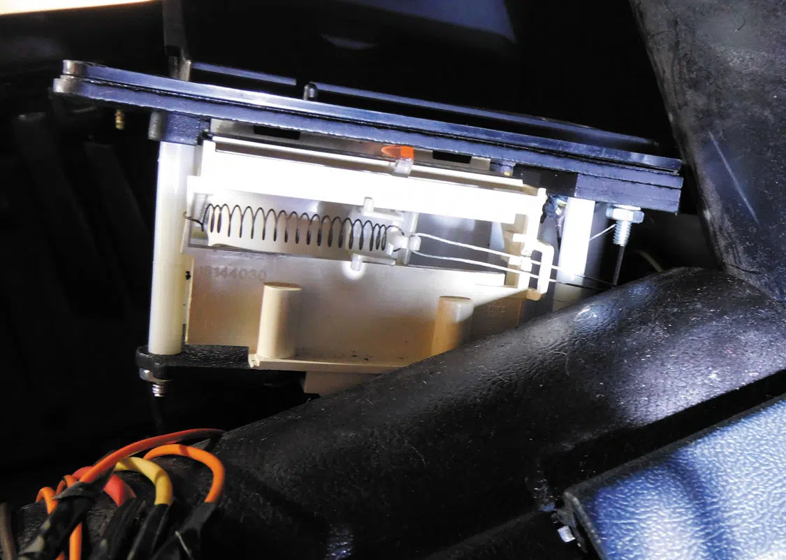
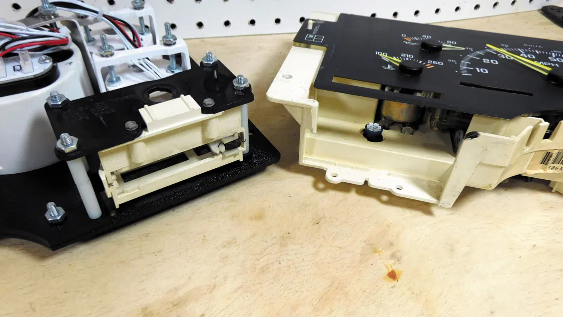
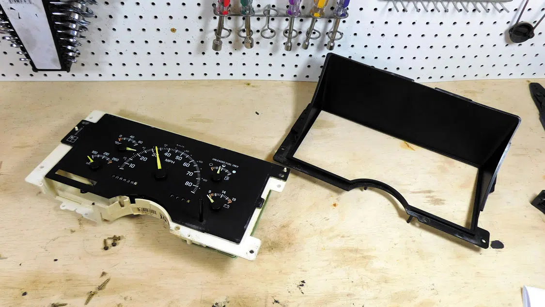
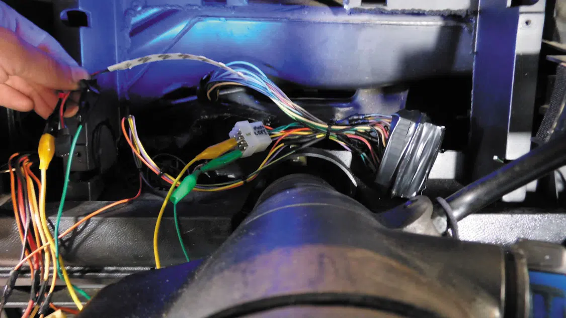
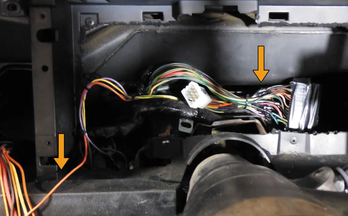
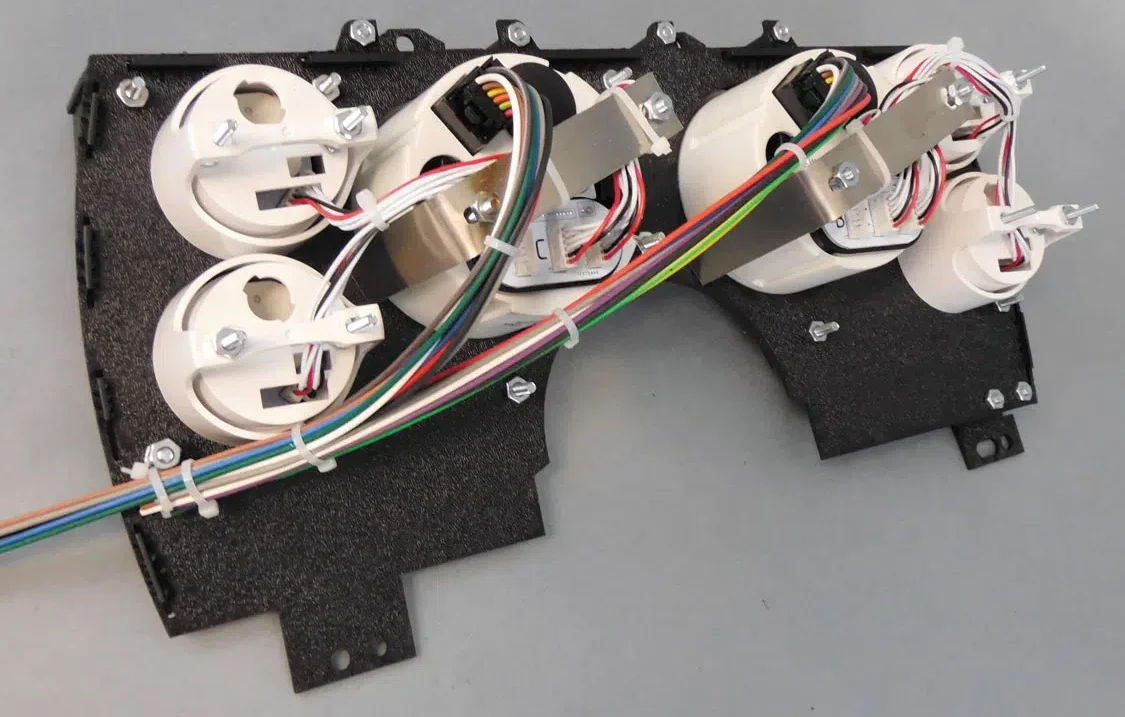
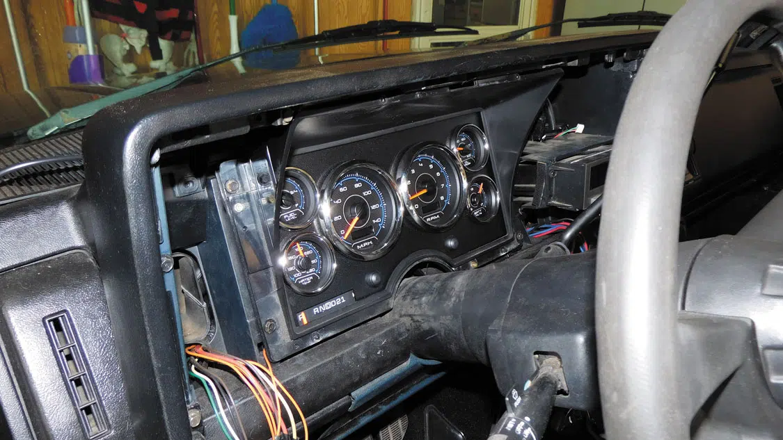
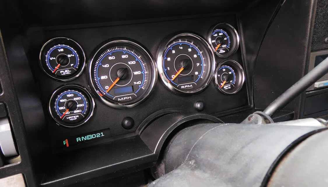
We are all about cool gauges, so we had to decide what series of gauge would help define our interior. The original gauges looked dated, and we needed to make sure our LS engine was properly monitored. New Vintage CFR Series blue gauges were chosen, and we wanted to share our installation process with you. This entire installation was done in our garage without any special tools.

1. We chose the New Vintage USA CFR Blue Kit (Part #89311-05) to do something a bit different and change up the look of the dash. The unique design will be the basis for the rest of the de-sign choices we make on the truck. New Vintage USA has kits for ’88-’94 and ’95-’98 GM OBS trucks in a wide variety of unique, bold styles to look great in your build.
2. The original cluster needed some attention, so the CFR Series gauges would give the dash a nice, updated look, and keep our LS engine functions monitored properly. The New Vintage USA gauges have plenty of modern features including performance timers, turn signals, high beam, warning lights, shift indicators, and much more.
3. The kit includes the pressure and temperature senders that match New Vintage USA gauges. Always use the matching sender for the gauge as the OE units will have different ranges which will not work on other instruments. Also shown is NVU’s LS Kit (Part #99009-04), which will adapt aftermarket senders to the LS ports. The temperature sender is M12x1.5 and the oil pressure M16x1.5.
4. Prep begins with the temperature and pressure senders. Use some high-temp thread sealant and apply an even coating to the threads. Leave the first few threads free of sealant to ensure a good “bite” into the engine. Do not use Teflon tape as it will degrade under heat and can cre-ate a bad ground, causing poor sender performance and inaccurate readings on the gauge.
5. The senders may need adapter bushings (NVU includes quarter-inch, three-eighths-inch, and half-inch bushings) to install in the engine. We are using the NVU LS Kit here. To prevent dam-age to the sender and bushings, you should always bench-install the sender in the bushing. Hold the bushing in a vise and tighten the sender until snug. Some sealant will creep out of the top threads, indicating a good seal.
6. There are two ways to install an oil pressure sender on an LS/Vortec engine. The first method is to replace the stock sender. It’s located on the upper rear of the block, passenger side.
7. Here you can see the sender location, next to the cam position sensor. When installing the new oil pressure sender, remember to always tighten from the bushing, not the sender, to avoid damage to the sender and/or bushing.
8. If the engine has been installed, spend the $10 and get the oil pressure sensor socket. The sen-sor has rounded corners, so it is a bit of a struggle to remove without the proper wrench. If the engine is out of the vehicle, you can use a standard wrench to remove it.
9. Alternatively, the oil pressure sender can be installed on the block-off plate just above the oil filter. The plate can be drilled and tapped, or do what we did—use this adapter piece and in-stall the sender here as we wanted to retain the oil pressure reading on the Holley 3.5-inch screen.
10. Most V-8 engines have at least two coolant temperature ports that are usually on the end of the cylinder heads and/or the block. On anything using fuel injection, the PCM requires a cool-ant sensor for adjusting various engine parameters. GM usually has this sender on the driver-side front. We will leave this in place so that the computer can monitor and adjust as needed.
11. Most cylinder heads use the same casting side to side, just flipped around 180 degrees, which leaves a port on the rear of the passenger-side head that can be used. Clean any debris from the 8mm hex head and remove the M12x1/.5 plug fitting.
12. Once the plug is removed, some coolant may drain from the head. Don’t worry, we can top off as needed later. Clean the area so that the flat sealing washer on the adapter can sit properly on the head. Use high-temperature thread sealant on the adapter and install it in the head. Use a wrench on the adapter, not the sender, when installing to avoid damage to the send-er/bushing.
13. Crimp the connectors on the sender wire and run into the cab. When running wire, leave some slack for engine movement whenever there is a transition from engine to vehicle.
14. Remove the 4 T-15 torx screws holding the dash cover plate. Pull out and disconnect the three switches on the left side of the dash. The dimmer switch also clips out of the dash from the back, so that may be easier than the plug itself.
15. We have removed the cluster for clarity. Remove the four 8mm screws (arrows) and the cluster pops right out. The plug shown is not clipped into the gauge assembly. Depending on your truck, you may have to remove the radio to access the upper right screw.
16. If you have an automatic column shift, the shift cable needs to be disconnected from the PRNDL assembly. Use some needle-nose pliers and unhook the cable loop from the clip, which snaps out by grasping the cable with the plier jaws.
17. Now you can move the original PRNDL assembly to the NVU bracket. Remove the two screws, slide out from the bottom, and re-install in the new bracket. The NVU kit also includes a light-bulb with terminals, so the shift position will still be visible at night.
18. Remove the factory bezel and lens from the original cluster. We will re-use the bezel on the new gauge setup for a nice factory fit. The NVU gauges have real glass, and that will be your new lens.
19. If you have a repair manual that has your wiring diagram, that is a great place to start. With so many variations on trucks, it’s difficult to find out the exact wiring schematic to use. The great thing about these trucks is the printed flexible circuit has everything labelled for you. Just trace the items back to the plug and connect there.
20. Here we are using some LEDs as a test light to verify the pinouts on the cluster. LEDs are polari-ty sensitive, which makes it easier to determine power and grounds. Start with power, ground, lights, turn signals, and then work your way to the senders.
21. This is where we spliced it into the factory harness. You can cut and crimp, but we opted to leave the factory plug in place in the event we need to get in there and figure something out later. The connections are soldered and taped, and then we will wrap the end in electrical and cloth anti-chafing tape. The orange wire on the left is for the lighting. Always use the parking light circuit when using LED lighting in gauges.
22. This is the best part when installing all NVU kits: The minor gauges simply plug into the speed-ometer and tach; then the two main harnesses are color-coded to splice into the vehicle.  Once your two main harnesses are sorted, just plug them in and the wiring is complete!
23. Attach the original bezel to the new bracket assembly with the supplied or OE screws. Plug in the wiring harnesses, attach the shifter cable, and set in place. Secure to dash with original or included screws.
24. Reinstall the factory pieces: radio, switches, bezel, etc. We will be adding on an AFR, boost, and EGT gauge in the next stage. Luckily, NVU offers all of the add-on gauges that have the same CFR design so we can have a nice cohesive look.
25. Everything is installed. Now, all we need to do is power up the gauges and set up our tach and speedometer. New Vintage USA makes this super easy. All the setup menus are step-by step and clear to follow along on the OLED displays. These look great, and with the hidden turn sig-nals, high beam, and indicator lights, it works just like a modern cluster with some added class.

THE DETAILS

Vehicle Owner:
Mark Surel

Build Shop:
Mark’s barn

Gauges provided by:
New Vintage USA
248-850-5482
www.newvintageusa.com

PARTS LIST

#89311-05: New Vintage USA ’88-’94 GM Truck Kit, CFR Blue
MSRP $879.99

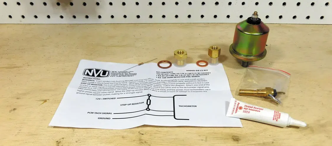
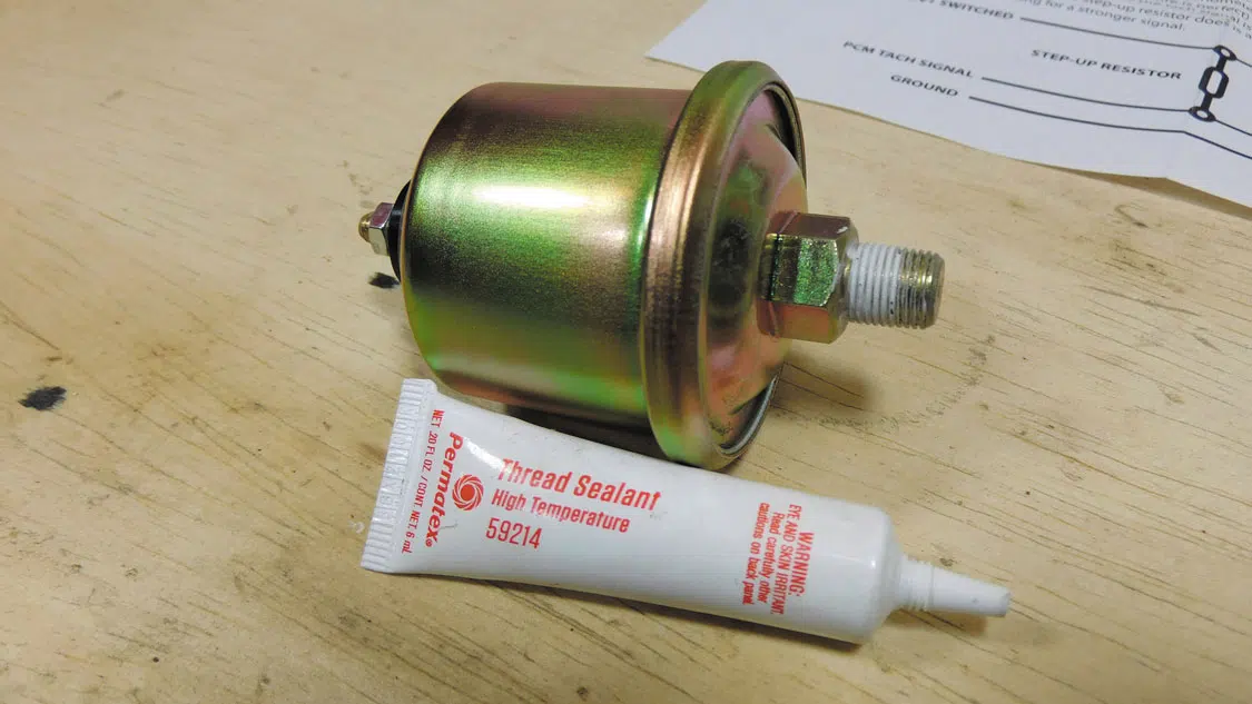
#99009-04: New Vintage USA LS Kit
MSRP $72.59
Miscellaneous wire and connectors


Share your EVENT!
Official Motortopia Event Schedule
SHOW US YOUR RIDE!
There was a problem with your