 JERRY MCFARLAND
.
August 09, 2021
.
OBS Builders Guide
JERRY MCFARLAND
.
August 09, 2021
.
OBS Builders Guide
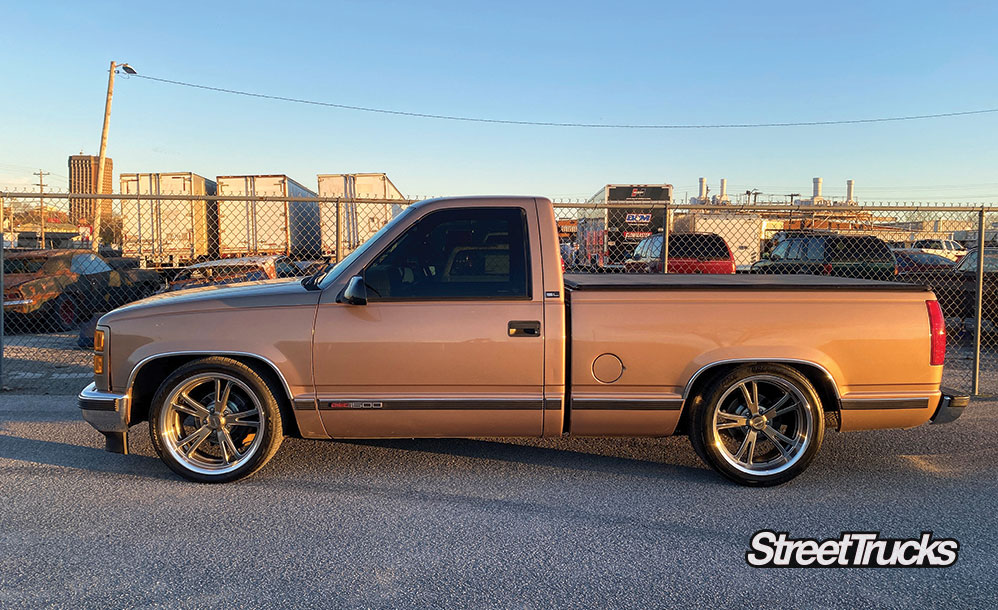
When it comes to lowered trucks, the stance is everything! Without the proper stance, the truck will not look good or handle correctly. One company has been getting it right since 1983—Belltech.
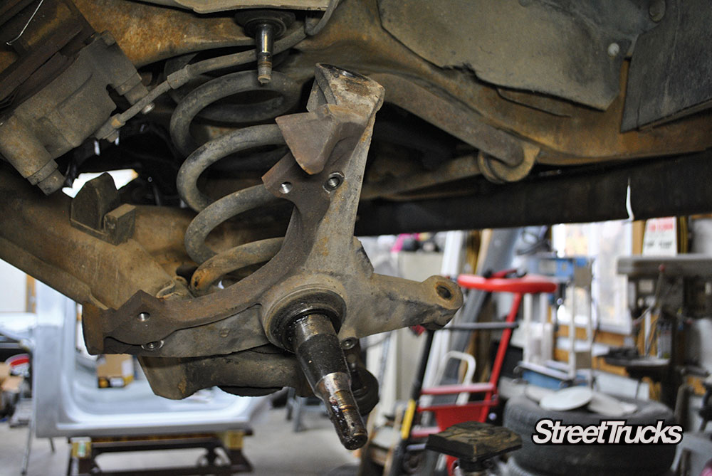
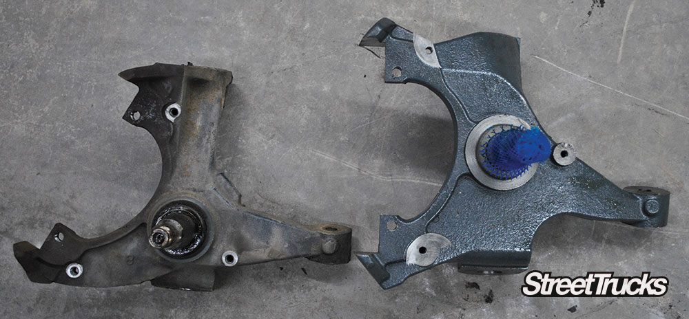
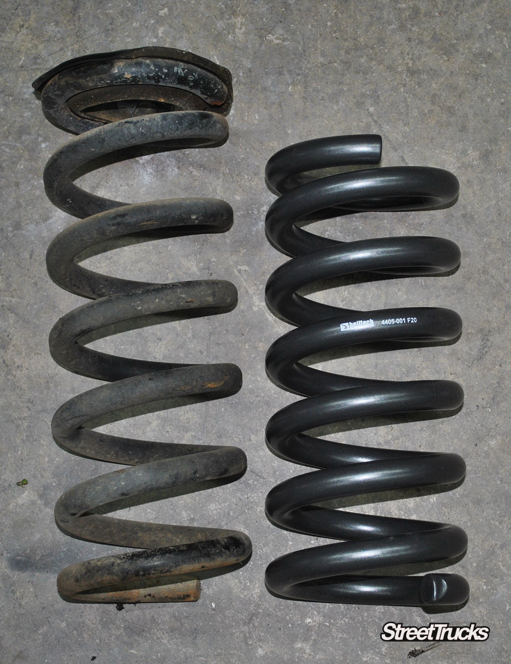
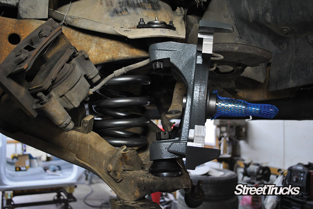
Belltech was at the forefront of the sport truck craze in the early ’90s building parts for none other than the GMT400 trucks. The launch of the drop spindle allowed people to lower their trucks while maintaining front-end geometry. They also addressed the rest of the suspension with shackle kits, flip kits and lowering coil springs. All of these components resulted in a ride quality that hadn’t been realized before now.
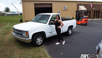
We recently picked up a 1996 GMC Sierra C1500 as a project truck. It was a bit rough around the edges but had great bones and potential. A little elbow grease and replacing a few things such as the carpet and body side moldings had the truck looking much better than when we bought it. The next step was to address the suspension, brakes and wheels.
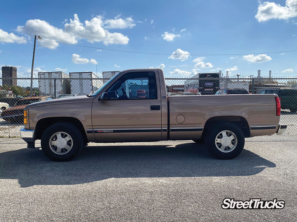
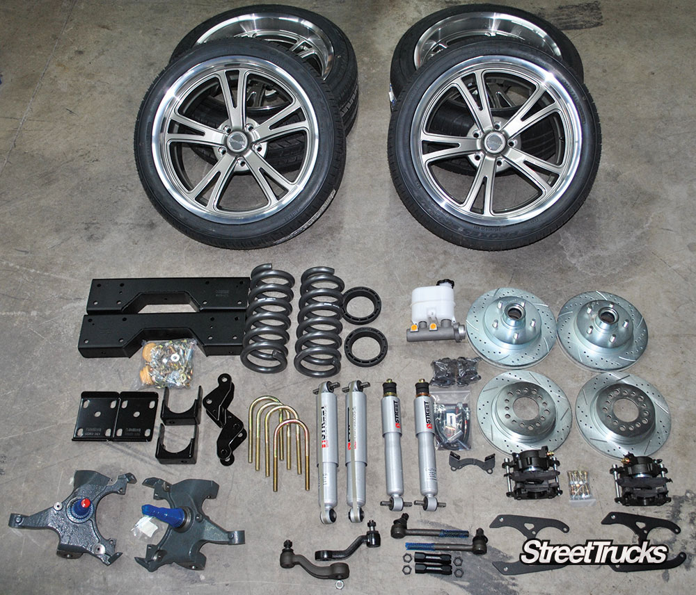
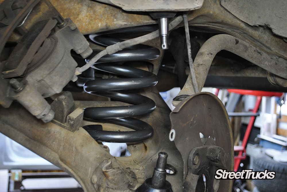
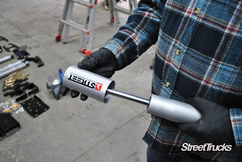
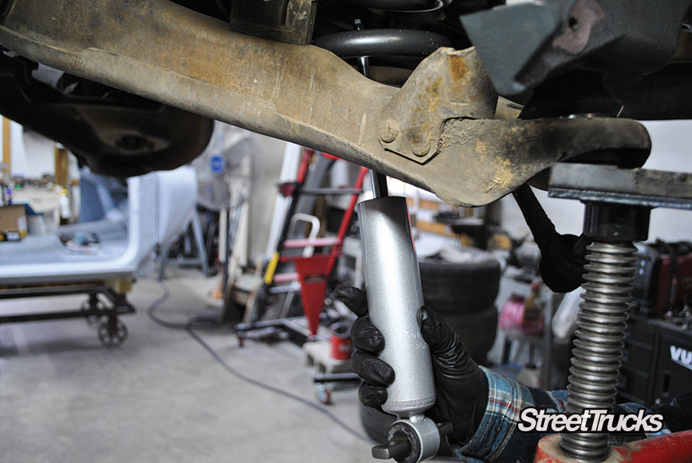
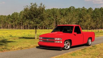
To get the stance and look we wanted, we reached out to our friends at Belltech and Ridler wheels. We knew we wanted it to be low, but didn’t want to lay frame. The folks at Belltech recommended a 4/6 lowering kit with their Street Performance shocks part #688SP. We chose the new Ridler 606 gray with milled spoke wheels wrapped in Toyo rubber to round out the look we were after.
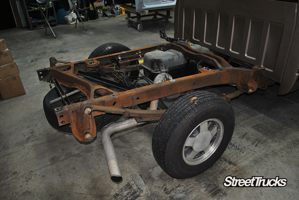
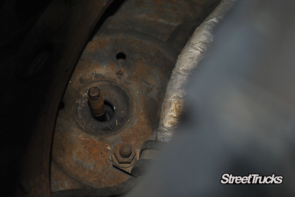
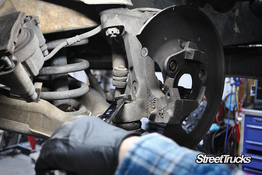
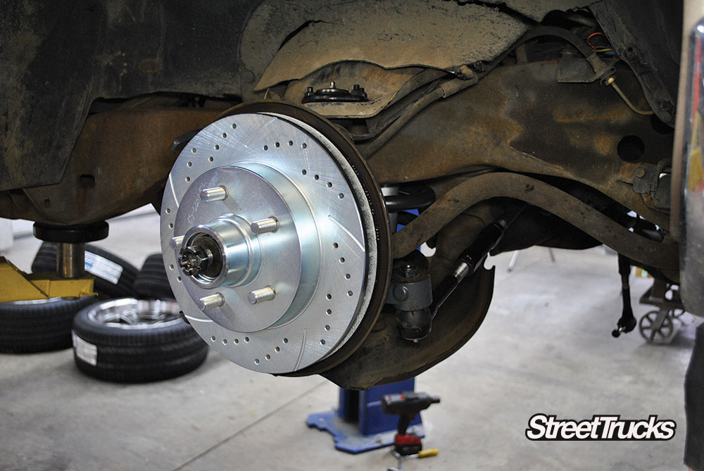
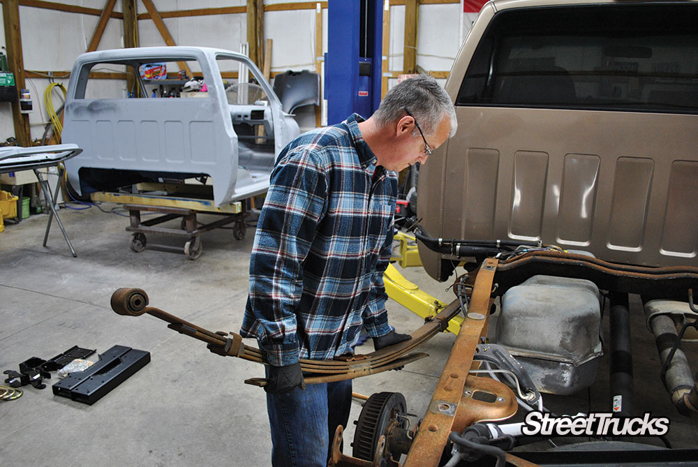
While we were tearing into the suspension, we also decided to upgrade the brakes and steering components. We chose drilled and slotted front rotors and a rear disc conversion from Little Shop Manufacturing. To ensure the truck steered straight and true, new steering components and balljoints were in order from Proforged.
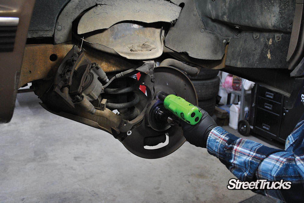
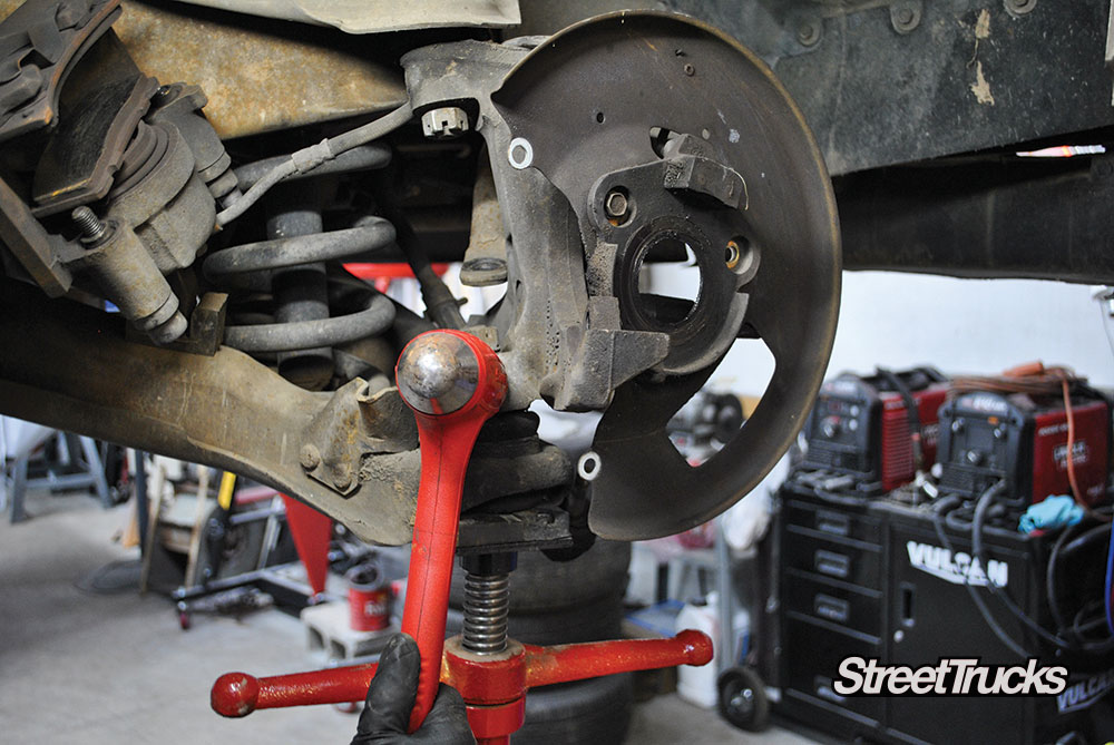
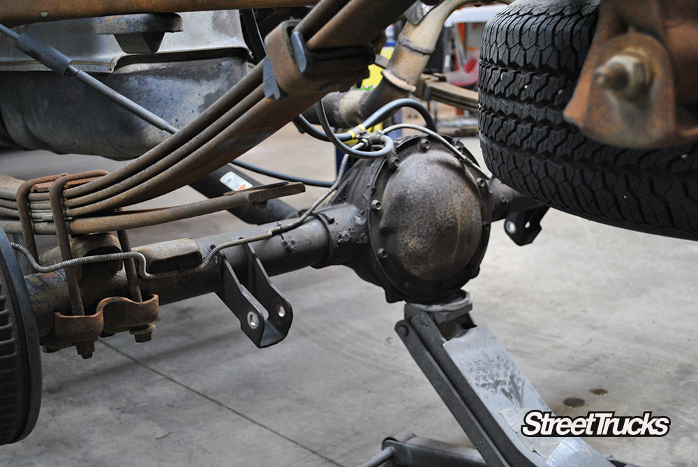
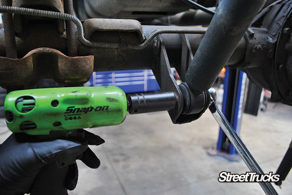
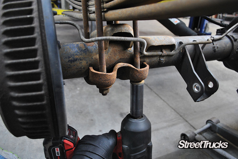
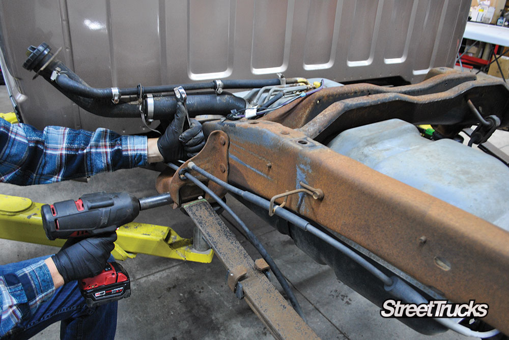
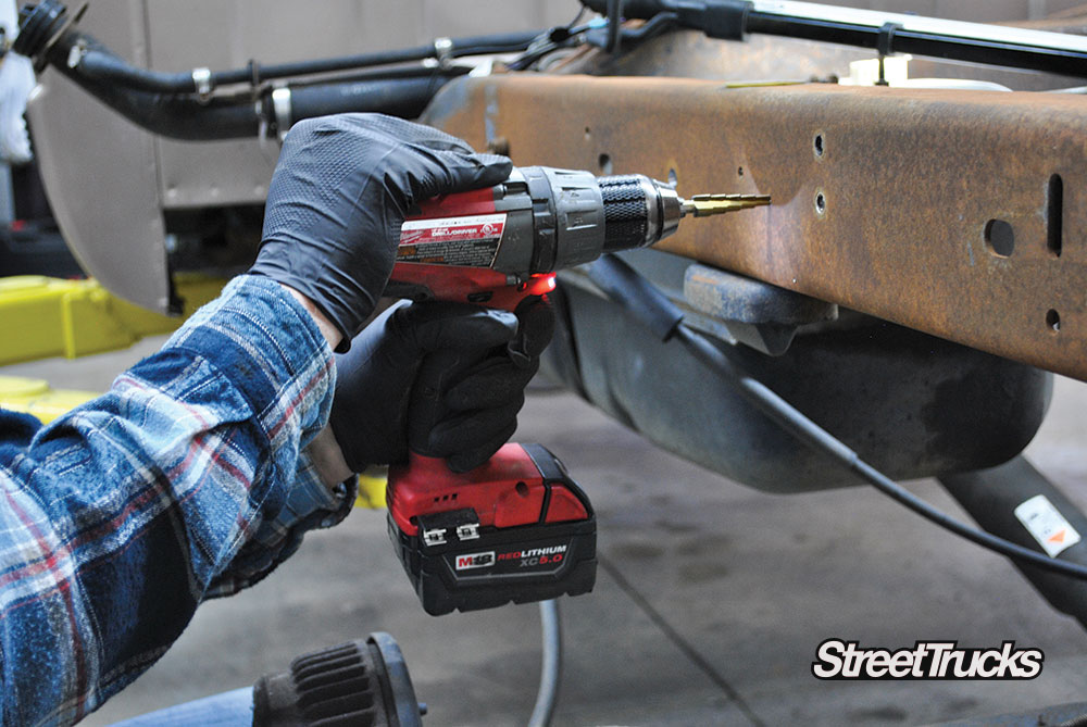
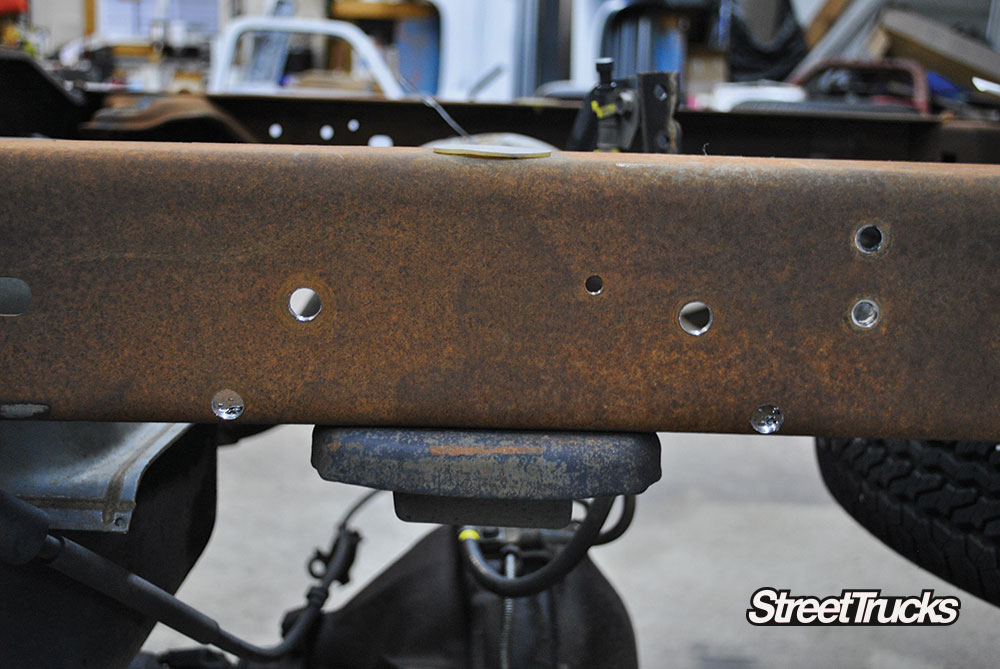
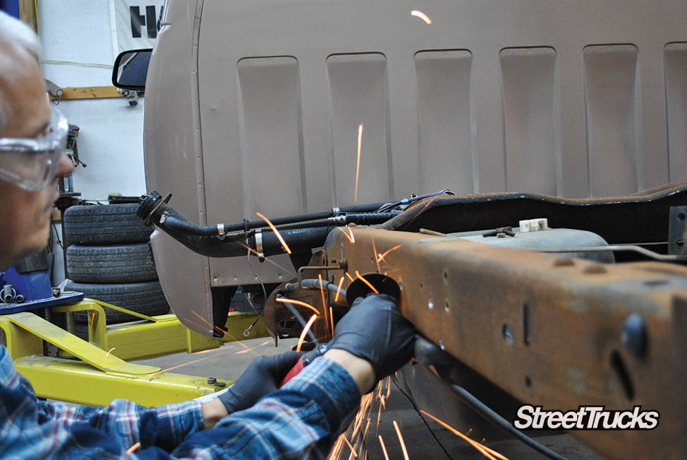
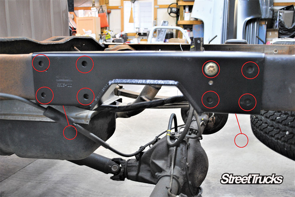
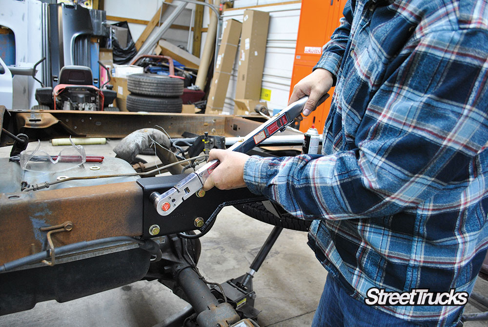
All of these parts combined are going to create a truck that handles as well as it looks. Lets dive into what it takes to istall a 4/6 lowering kit from Belltech.
Check out other Belltech lowering tech installs click here!
Sources
Belltech
www.belltech.com
800-445-3767
Ridler Wheel
www.ridlerwheel.com
866-894-3351
Proforged
www.proforged.com
866-464-6553
Little Shop Manufacturing
www.littleshopmfg.com
OBS Builders Guide
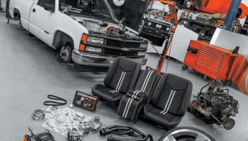
Back to our favorite project of 2020! To catch everyone up, Stella is a 1995 Chevy C1500 truck with no major issues when we picked… Continue reading
Chris Hamilton . May 12, 2020
OBS Builders Guide
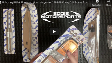
Billet Aluminum Hood Hinges for 1988-98 Chevy C/K Trucks Fits 88-98 C/K Chevy/GMC Trucks 92-99 Blazer/Jimmy/Suburban/Tahoe Yukon ●High strength, precision billet aluminum construction ●Utilizes sealed… Continue reading
Chris Hamilton . April 30, 2020

OBS Builders Guide
A Street Truck Aimed to Inspire The classic movie, “A Streetcar Named Desire,” was recently selected for preservation in the United States National Film Registry… Continue reading
Chris Hamilton . September 02, 2020
Events
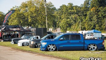
EVENT RAISED $4000 AND 130 FUNKO POP FIGURES FOR POPS FOR PATIENTS The Sparks Show 2020 at the Sevier County Fairgrounds in Sevierville, Tennessee, brought… Continue reading
LOGAN WADE . April 21, 2021
OBS Builders Guide
The Evolution Of The OBS What Is The Major Differences in ’88-’98 Chevy Trucks? In my opinion, 1988 was the exact year that jump-started the… Continue reading
CHRIS STAFFORD . September 07, 2021
OBS Builders Guide
On Every Kid’s Wish List in the 1990s How many of you wanted a Red Ryder BB gun after “A Christmas Story” appeared on TV… Continue reading
Chris Hamilton . June 06, 2022
Goodguys 35th Speedway Motors Heartland Nationals Presented By FiTech Fuel Injection
Iowa State Fairgrounds 3000 East Grand Avenue, Des Moines, IA 50317
Goodguys 28th Summit Racing Nationals Presented By Grundy Insurance
Ohio Expo Center 717 East 17th Avenue, Columbus, OH 43211
Stray Angels Show & Shine
Stray Angels Show & Shine at Melrose Vineyards 885 Melqua Rd. Roseburg OR. 97471
43rd Annual Stray Angels Show & Shine
Melrose Vineyards, Roseburg, Oregon
Firecracker Car Show
Pioneer Park, Ferndale, WA
We use cookies to enhance your browsing experience, serve personalized ads or content, and analyze our traffic. By clicking "Accept All", you consent to our use of cookies. Visit our Cookie Policy for more info.
 Please wait...
Share Link